Digital Production: Data Continuity from Design to Manufacturing
Data continuity becomes process continuity
"Increase your degree of automation and increase productivity," was the previous motto. True, but the productivity gained is lost again if, due to a lack of data continuity between departments, e.g. information already defined in design cannot be used in robot programming. This is particularly important in the case of design changes or when programming variants.
The big digitization projects are making headlines. However, when I am on the road as an expert for the digital factory in manufacturing companies, I see a lot of paper, 2D drawings containing manufacturing information, manually maintained Excel lists and "trial and error" up to the first good part.
This not only reduces productivity, but also makes the rollout of new digitization strategies difficult or even impossible. That's why I recommend to my business partners to modernize their working methods and technologies in order to approach the ideal of a continuously digitalized value-added chain. Only then can you fully exploit the potential of your Company.
Where are the interface problems in the value chain?
Actually, this topic is not new. In machining, a close connection between CAD and CAM has been common practice for years. Surprisingly, this still does not apply to robot-based applications. The following are some typical fields of action in the area of data consistency that I regularly observe in practice and that have a direct impact on shop floor productivity.
The passing on and processing of data is made more difficult because, among other things:
- For each engineering phase a different software is used, which does not offer standardized cuts and thus causes media breaks.
- A different software is used for each engineering phase, which does not offer standardized interfaces and thus causes media breaks.
- CAD data of the component only represent the product constructively, so that separate production drawings often have to be created for production.
- Production planning and process specifications often take place in Excel or other non-integrated tools.
- Proprietary PLM systems realize horizontal data consistency, but often do not offer special functionality for vertical processes and technologies.
- Typically there is no complete digital twin of the plant (among other things, 3D geometry of the components, kinematics, I/O connectors, behavior models are missing) and consequently neither exact OLP programming can be carried out, nor data for PLC validation and virtual commissioning is available.
These are examples, the list could be extended almost arbitrarily. You know best where the central problems for the current setup and future strategy of your company lie.
Continuous digitization of processes for welding production
A concrete example shows how effective already some obvious changes in processes and technologies can be.
How about automating and digitizing your welding production from the CAD authoring program to series production? If you do not only introduce an OLP solution but also modernize the most important processes?
First of all, the workflow as it is typical in many workshops today:
- The new component or component variant is created in the CAD authoring program. The designer defines parameters such as weld seam type, start and end point of the weld seam and weld seam thickness for subsequent welding production. It stores this information in a separate 2D weld seam documentation of the component.
Problem: Because there is no 3D master, it depends on the daily form of the designer whether he considers and enters all necessary data. - The colleagues in production take over the 3D data of the component and sift through the weld seam information. They must then use the 2D documentation of the component to determine where the weld seams are located on the real component.
Problem: Errors are easily possible during alignment. Or there is a mix-up and the wrong document is used. - The robot cell is programmed via teach-in. The employee sets the welding seams and their respective start and end points.
Problem: The exact positioning of the welding seams is difficult and contributes to the high expenditure of time of several man-days. This is also because the correct position, type and length of the welds must always be taken into account when developing the optimum program sequence. At the same time, it is important to consider which welding sequence is most efficient.
There's no other way! The solution lies in the digital transformation of this process.
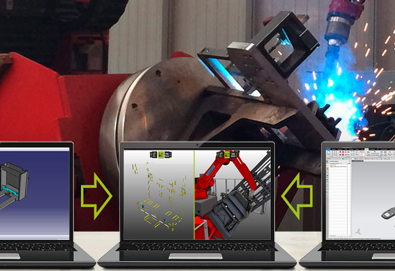
- The design department uses a 3D master. It contains not only the geometric representation, but also all relevant manufacturing and planning information. As a result, all the necessary information is already available within the 3D model and is stored consistently.
Result: High process reliability and no media breaks to manual processes. - A process-specific additional program analyzes this 3D master and transfers the welding seams of the component, including the parameters created by the designer, automatically from the CAD system to a neutral format without loss.
Result: The data is digitized and can be passed on error-free with all necessary information about the weld seam. - The cell is programmed offline with FASTSUITE Edition 2. For this purpose, the employee imports the CAD data and the weld seam data from the neutral format.
Result: FASTSUITE Edition 2 automatically sets the weld seams and the associated parameters during programming. Manual definition is no longer necessary! The amount of work is considerably lower and the work quality much higher, since the welds are exactly as intended by the designer. - A further increase in quality in the overall process can be achieved because we can extend FASTSUITE Edition 2 customer-specifically so that the position of the weld seam is automatically adapted to the tool path when changes are made to the component (e.g. length and/or width). This means that adjustments of the tool path to changed component sizes can be easily implemented and are also possible after importing the process geometry.
Result: The back loop to the design is not necessary for minor changes to the weld seams.
Savings and better processes mean fast ROI
Estimate what savings will be achieved and you can easily imagine that the return-on-investment is not a long-term goal, but will be achieved after only a few months, depending on the specific project.
In addition, there are satisfied customers who appreciate your relaxed reaction to changes, employees who are happy about new successes at their workplace, and a plus in the sustainability of your business processes.
As already mentioned, the description of the welding process is exemplary. As the FASTSUITE® team, we can assist you with a wide range of manufacturing technologies.
If you want to set out on the road to digital manufacturing, we can provide you with comprehensive support.
CENIT's core competencies for this task include
- Comprehensive consulting within the production processes
- Deep knowledge of various CAD authoring programs
- offline programming with the simulation software FASTSUITE Edition 2
- customer-specific software development Made in Germany
- a broad knowledge of methodology
Start modernizing now!
Our consultants turn these services into a team effort that will drive your successful digital transformation forward.
Media disruptions and non-digitized processes prevent people and machines from working efficiently. Manual entries increase the susceptibility to errors, limit flexibility and slow down the simplest processes.
Start by overcoming digital weaknesses and take your automation to a new level with us.I look forward to getting to know your challenges!