


Model-Based Definition: Take Your Engineering Processes to the 21st Century

Are you creating tomorrow’s products with yesterday’s processes?
The lack of digital continuity is holding back your engineers, and media breaks impede collaboration with your customers and suppliers. You’re not the only one with this problem - legacy workflows from the analog era still linger in many mid-sized manufacturing companies. Many aspects remain to be digitalized and some aren’t even digitized. Model-based definition is your key to resolving this problem from the ground up.
Lag-free, agile and connected: That’s how we picture a modern engineering workplace in cutting-edge tech sectors like automotive or mechanical engineering.
But so far, that image doesn’t reflect reality. Even today, only a few businesses and startups have installed a digital backbone that connects all the disciplines and is used to consistently generate, update and review product lifecycle Information.
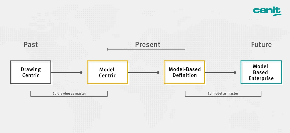
From 2D Drawings to Model-Based Definition: The Next Step in Evolution.
Relics from the drawing-board era: 2D drawings as masters
One of the hurdles on the path to end-to-end engineering is the continued use of the paper-based 2D technical drawing to pass on data relevant to production, quality and function.
It remains the standard working tool even though it has a decisive drawback: It represents a media break vis a vis the 3D models used by CAD authoring systems to engineer components and assemblies.
As a deduction from the CAD 3D model, the drawing is already a simplified interpretation in itself. To use drawings, engineers have to “read” them and thereby interpret them once more.
If design guidelines are missing, too much depends on experience
The problem is compounded by the fact that design guidelines are often no longer up to date. In some instances, they doesn’t exist at all. The purpose of such guidelines is to define, in accordance with the relevant industry standards, how the respective business manages its technical product information. Without guidance, engineering experience becomes the only basis for value addition: If the engineers know their colleagues well, they are familiar with their peculiarities and understand their way of doing things. But then what happens when key employees leave the company?
For illustration, let’s assume that the tool shop does not correctly adopt the reference scheme that the designer has given the component – either because the specification is already incorrect in the 2D drawing or because it was misinterpreted. After a few processing steps using an incorrect tilt angle, the components have to either be discarded or elaborately retooled.
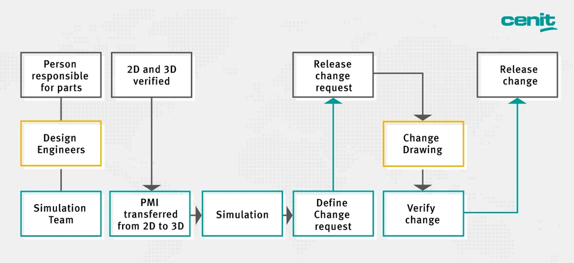
2D Drawing as Master (Image 1): In this example, three departments are involved in the tolerance inspection of a component. There are five handovers and a 3D-to-2D media break.
Tolerance testing of components – with and without 2D drawings
What changes when you make the 3D model your “single source of truth” master, containing all data relevant to manufacturing, quality and function (PMI - product and manufacturing information)? To clarify this, we can look at a standard process: tolerance testing of a component.
Usually (Fig. 1), the person responsible for the parts (orders testing / releases a change request / releases change), the simulation experts (manually transfers PMI values from 2D drawing to testing software / describes the change request / checks change from development department) and the design department (changes PMI in 2D drawing) are involved in this process several times.
Because the 2D drawing (being the master containing the PMI) must be changed, we incur a media interruption vis a vis the 3D model.
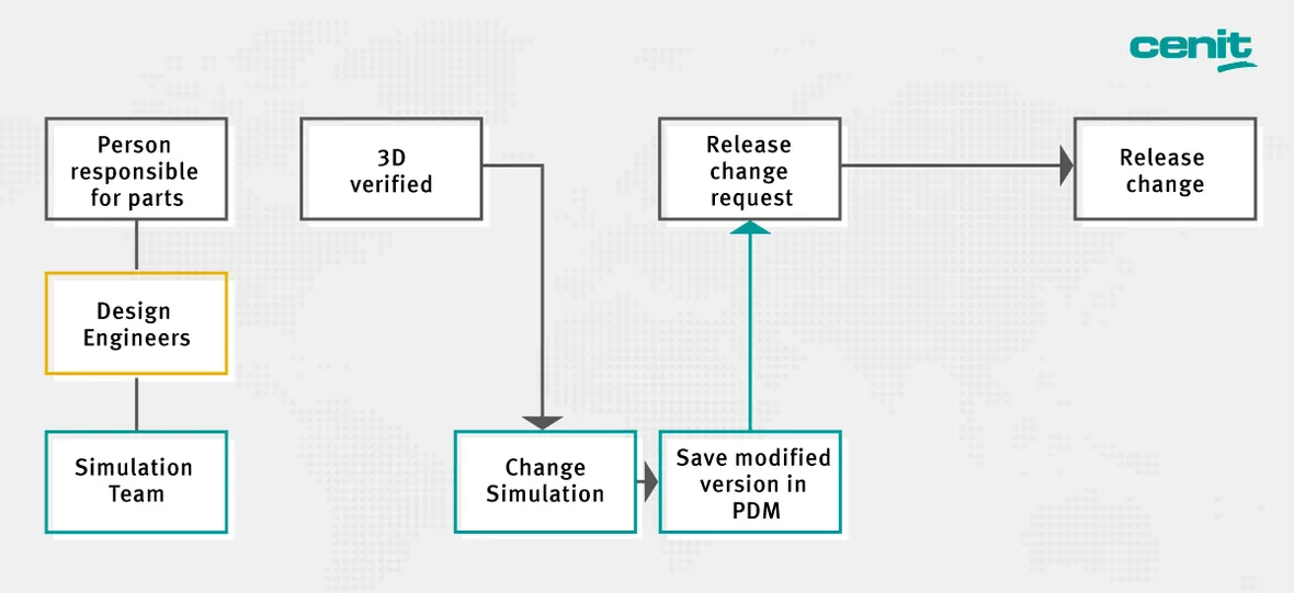
In future (Fig. 2), the process unfolds as follows: The simulation experts upload the relevant PMI data they have obtained with the 3D model to the tolerance software. Changes to the PMI are again entered directly into the 3D model and filed in PDM (product data management). Once the engineer responsible for the parts releases the change, the process is already completed.
You thus eliminate non value-adding steps and avoid media interruptions that reduce your productivity and always pose risks regarding the consistency and correctness of your data.
Instead, PMI values for individual components can now be automatically input into downstream software applications, letting you digitally link associated processes.
This isn’t just more efficient, it’s also an urgent requirement if you are planning to expand Industry 4.0 scenarios in your business. But saying a final farewell to the last 20th century processes and going full-on digital with your engineering is one thing. To be ready for connected applications, you also need to consistently digitalize your processes.
Harnessing model-based definition to modernize your product development process
How then do you upgrade your product development processes to achieve this degree of digital maturity?
The framework for this project is determined by three fields of activity:
- Starting model: You define or update your starting model. This means specifying a standard regarding the data which has to be generated for a component. This uniform data model must be a complete description of the product and contain all information needed in downstream processes.
- Design guidelines: You define or update the standardized and uniform approach associated with this starting model.
- Model-based definition: You record all manufacturing, quality and function-relevant data in the 3D model of the component (see also Geometrical Product Specification, ISO GPS). This must ensure data associativity, i.e. the PMI is assigned to specific components. The data are machine-readable and can be utilized as digital input in downstream processes.
Introducing model-based definition is the only way to replace the 2D drawing as master. And working with model-based definition is the only way to fully integrate your product development process with any closed-loop process control via your digital backbone.
Think big – start small: Correct project dimensioning
Generally, you only ever need to convert specific component groups and processes, rather than trying to take on your entire inventory list. After all, the project means intervening with tried and proven processes, and it will require changes to your PDM and PLM systems.
Additionally, you want the project to pay off in terms of digitalization. Currently, not all of your downstream processes are prepared for data intake and dispatch.
This can be due to a lack of standards – there’s plenty to do in that sphere. Or it may simply be the result of well-functioning but outdated equipment: perhaps your measurement machine dates back to a time when nobody thought of asking about open data interfaces.
And there’s another aspect to consider: You may well have internal divisions that will be unable to operate without 2D drawings in the near future, and the same applies to some external partners. Also, the limited information content of 2D drawings has its advantages in terms of intellectual property protection.
In the latter regard, we recommend generating 2D drawings from the current data status using a process-driven conversion system, and marking them with an appropriate stamp.
Upgrade your engineering now – with CENIT as your Partner!
A project like this gives rise to a great many questions, including business decision-making, process modulation regarding development, manufacturing and IT, and initiatives needed to bring staff on board.
We would be pleased to support you in this process with our “Ready to” packages. With more than 30 years of experience in the manufacturing industry, CENIT stands for deep, networked expertise on the product development process.
Our “Ready to” services give you a clear path to success:
- rapid implementation based on generic project component
- solutions based on pre-configured templates and standard settings
- clearly defined project outlay